How to Convert Solid 3D Designs to Flat Sheet Metal
Designing in 3D is a common practice in industries like automotive, aerospace, and consumer products. Often, these designs need to be converted into flat sheet metal for manufacturing. This process can seem complex, but with the right steps, it becomes much simpler. In this blog, we will walk you through the process of converting solid 3D designs to flat sheet metal using SOLIDWORKS, a popular design software.
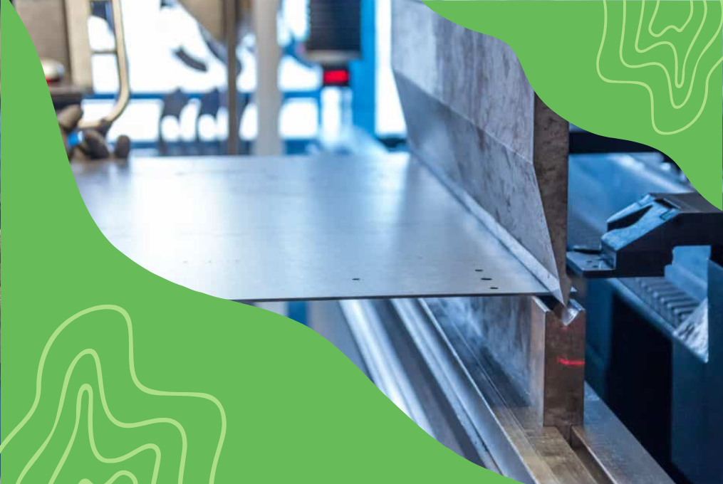
Understanding Sheet Metal
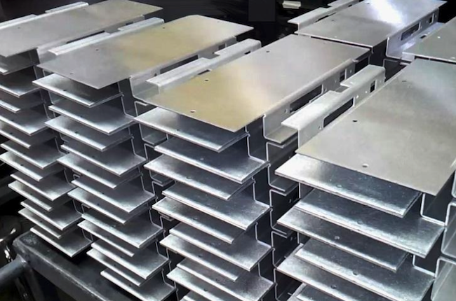
Sheet metal is a thin, flat piece of metal that can be easily cut, bent, and shaped. It is widely used because it is strong, lightweight, and cost-effective. Converting a solid 3D design into sheet metal helps in making the part easier to produce and assemble.
Why Convert to Sheet Metal?
Converting solid 3D designs to sheet metal is beneficial for several reasons:
Cost Efficiency: Sheet metal parts are cheaper to produce.
Ease of Manufacturing: Sheet metal can be easily formed into the required shapes.
Simplicity in Assembly: Flat parts can be bent and assembled more easily.
Steps to Convert Solid 3D Designs to Sheet Metal
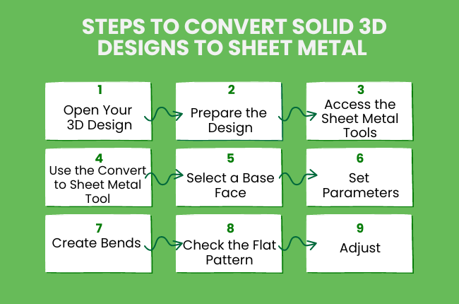
Open Your 3D Design: Start by opening your 3D design in SOLIDWORKS. Ensure that your design is complete and ready for conversion.
Prepare the Design: Simplify your design by removing any unnecessary features. This includes fillets, complex cuts, or small holes that might complicate the conversion process.
Access the Sheet Metal Tools: In SOLIDWORKS, navigate to the 'Sheet Metal' tab. If it is not visible, right-click on the tabs area and select 'Sheet Metal' to add it.
Use the Convert to Sheet Metal Tool: Select the 'Convert to Sheet Metal' tool. This tool allows you to convert your solid 3D design into a sheet metal part.
Select a Base Face: Click on the face of your solid part that you want to use as the base of your sheet metal part. This face will act as the foundation for your sheet metal design.
Set Parameters: After selecting the base face, you need to set some parameters:
Bend Radius: This is the radius of the bends in your sheet metal. Make sure it matches your manufacturing capabilities.
Thickness: Set the thickness of the sheet metal. This is the thickness of the metal when it is flat.
K-Factor: The K-factor determines how the metal will stretch during bending. The default value usually works well, but you can adjust it if necessary.
Create Bends: SOLIDWORKS will automatically create bends based on the selected parameters. This will convert your solid part into a sheet metal part with bends and flat surfaces.
Check the Flat Pattern: After conversion, check the flat pattern of your sheet metal part. The flat pattern is the unfolded version of your part, which shows how the part will look before it is bent.
Adjust: If necessary, adjust the bend radius, thickness, or other parameters to ensure the part is manufacturable.
Adding Features
Edge Flanges: Use the 'Edge Flange' tool to add flanges to your sheet metal part. This tool lets you extend edges to create additional features.
Cutouts and Holes: Use the 'Cut' tool to add holes or cutouts to your sheet metal part. This can be done in both the folded and unfolded states.
Forming Tools: SOLIDWORKS offers forming tools to add features like louvres, dimples, and ribs. These tools help in creating more complex sheet metal parts.
Final Steps
Generate Drawings: Once you are satisfied with your sheet metal part, generate detailed drawings. These drawings include the flat pattern and bending instructions.
Export for Manufacturing: Export the flat pattern and drawings to formats that your manufacturer can use. Common formats include DXF and DWG.
Wrapping Up!
Converting solid 3D designs to flat sheet metal in SOLIDWORKS is a valuable skill that simplifies the manufacturing process. By following these steps, you can easily transform your designs into sheet metal parts, making them more practical and cost-effective to produce. Happy designing!