Converting a Solid Part to a Sheet Metal Part in SOLIDWORKS

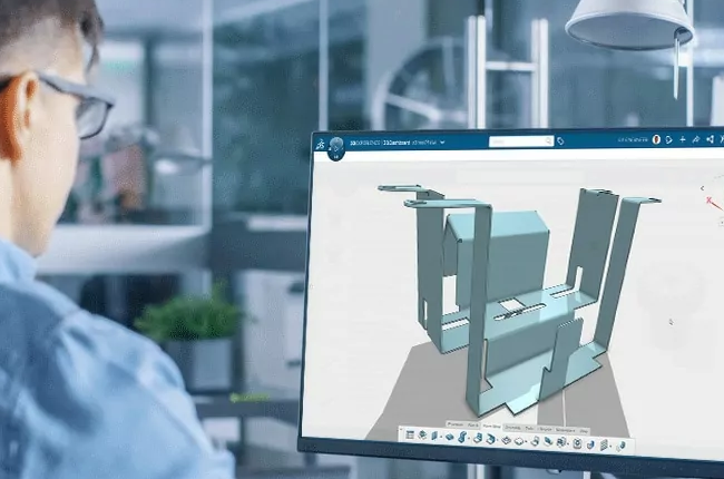
When designing products in SOLIDWORKS, you might find yourself needing to convert a solid part into a sheet metal part. This process is common in industries like automotive, aerospace, and consumer products, where sheet metal is frequently used. Converting a solid part to a sheet metal part in SOLIDWORKS can seem tricky, but with a few simple steps, it becomes straightforward. This blog will guide you through the process in an easy-to-understand manner.
Know About Sheet Metal?
Sheet metal is a flat, thin piece of metal formed through an industrial process. It can be cut, bent, and shaped into different forms. Sheet metal parts are widely used because they are lightweight, strong, and cost-effective.
Why Convert a Solid Part to Sheet Metal?
Sometimes, you might start with a solid model to get the shape and design right. But when it comes to manufacturing, sheet metal might be more practical. Converting a solid part to sheet metal can help in making the part easier to produce, reduce material costs, and simplify the assembly process.
Getting Started
Open Your Solid Part: Start by opening your solid part in SOLIDWORKS. This is the part you want to convert into sheet metal.
Prepare the Part: Ensure that your solid part is suitable for conversion. Remove any unnecessary features that might complicate the process, such as fillets, complex cuts, or small holes. The simpler the part, the easier it is to convert.
The Conversion Process
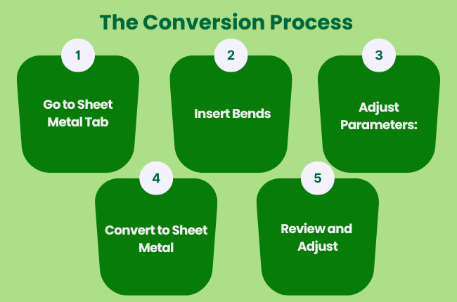
1. Go to Sheet Metal Tab: In SOLIDWORKS, go to the 'Sheet Metal' tab. If you don’t see this tab, you can add it by right-clicking on the tabs area and selecting 'Sheet Metal'.
2. Insert Bends: Use the 'Insert Bends' tool to start the conversion. Click on this tool and select the face of your solid part. This face will become the base of your sheet metal part.
3. Adjust Parameters: After selecting the face, SOLIDWORKS will ask you to set some parameters.
These include:
Bend Radius: This is the radius of the bends in your sheet metal. It should match the capabilities of your manufacturing process.
Thickness: Set the thickness of the sheet metal. This is how thick the sheet metal will be when unfolded.
K-Factor: This factor determines how the metal will stretch during bending. The default value works in most cases, but you can adjust it based on your needs.
4. Convert to Sheet Metal: After setting the parameters, SOLIDWORKS will convert your solid part into a sheet metal part. It will automatically create bends where needed and unfold the part to show the flat pattern.
5. Review and Adjust: Check the converted sheet metal part for any issues. You might need to adjust the bend radii or the thickness to ensure the part is manufacturable.
Additional Features
Adding Flanges: You can add flanges to your sheet metal part using the 'Edge Flange' tool. This tool lets you extend the edges of your sheet metal part to create additional features.
Creating Cutouts: Use the 'Cut' tool to add holes or cutouts to your sheet metal part. This can be done in the folded or unfolded state.
Using Forming Tools: SOLIDWORKS offers forming tools to add features like louvres, dimples, and ribs. These tools can help in creating more complex sheet metal parts.
Finalizing the Design
Once you are satisfied with the converted sheet metal part, you can create drawings and flat patterns for manufacturing. SOLIDWORKS makes it easy to generate these documents, which you can then send to your manufacturer.
Conclusion
Converting a solid part to a sheet metal part in SOLIDWORKS is a useful skill that can save time and reduce costs in the design and manufacturing process.
By following these simple steps, you can easily transform your designs and take advantage of the benefits that sheet metal offers. Happy designing!